Sep 4, 2024
Deploying AKS 2 – Creating and Configuring Containers
  1. Next, we have the Authentication tab; here, you will note we can modify the setting for the Authentication method type to either Service principal or System-assigned managed identity. This will be used by AKS for managing the infrastructure related to the service. For this exercise, we will leave this at its default setting. Then, you have the Role-based access control (RBAC) option. By default, this is set to Enabled; this is the best option to manage the service as it allows fine-grained access control over the resource; leave this as Enabled. You will also have the choice to enable AKS-managed Azure Active Directory. Checking this will enable you to manage permissions for users on the service based on their group membership within Azure AD. Note that once this function has been enabled, it can’t be disabled again, so leave this unchecked for this exercise. Finally, you have the option of the Encryption type value you want. For this exercise, leave it as the default setting. Click Next: Networking >. The process is illustrated in the following screenshot:
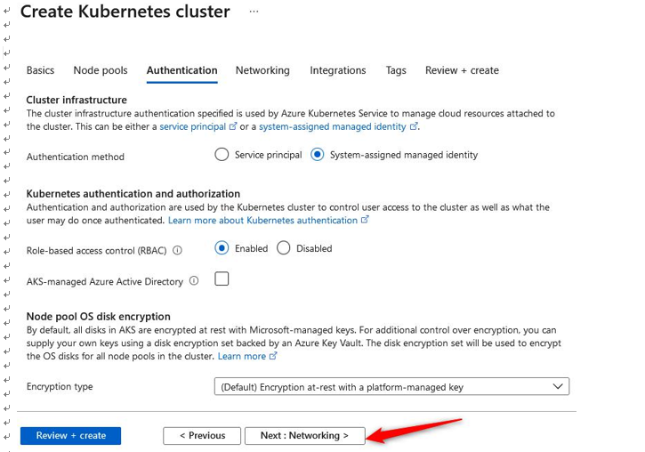
Figure 11.47 – Creating a Kubernetes cluster: Authentication tab

  1. For the Networking section, we will leave most of the settings as their default configuration. Note that for Network configurations we have two options here, one for Kubenet and another for Azure CNI. kubenet is a new VNet for the cluster whereby Pods are allocated an IP address and containers have network address translation (NAT) connections over the shared Pod IP. Azure Container Networking Interface (Azure CNI) enables Pods to be directly connected to a VNet. In association, this allows containers to have an IP mapped to them directly, removing the need for NAT connection. Next, we have the DNS name prefix field, which will form the first part of your FQDN for the service. You will then notice Traffic routing options available to us for the service—we will discuss this more in one of the next exercises, as well as the Security options available to us. Select Calico under Network policy. Click Next: Integrations >. The process is illustrated in the following screenshot:
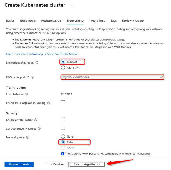
Figure 11.48 – Creating a Kubernetes cluster: Networking tab

  1. On the Integrations tab, you will note the option to select a container registry. We will select the registry that we previously deployed. You will also note you have the option to deploy a new registry directly from this creation dialog. Next, we have the option to deploy container monitoring into the solution on creation. We will leave the default setting here, but monitoring will not be covered under the scope of this chapter. Finally, you have the option of applying Azure Policy directly to the solution; this is recommended where you want to enhance and standardize your deployments. This solution enables you to deliver consistently and control your deployments on AKS more effectively. Click Review + create, then click Create. The process is illustrated in the following screenshot:
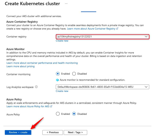
Figure 11.49 – Creating a Kubernetes cluster: deployment

You have just successfully deployed your first Kubernetes cluster; you now know how to deploy and manage containers at scale and in a standardized way. Next, we will look at how we configure storage for Kubernetes and make persistent storage available to our solution.

More Details
Feb 5, 2024
Security – Creating and Configuring Containers

Security

When configuring your network for AKS, you should consider the security components that also impact your design and management decisions. There are several items to consider (which we discuss in the following sections) that can improve the security of your containers.

Enabling a private cluster

For enhanced security, you can enable a private cluster. This ensures that trafficbetween your application programming interface (API) server and node pools is conducted over private network paths only. When configured, the control plane (API server) is run within the AKS-managed Azure subscription while your AKS cluster runs in your own subscription. This separation is key. Communication will thenoccur over a private endpoint (private link) from your AKS cluster to the private link service for the AKS VNet.

Setting authorized IP ranges

These are ranges that you will limit to accessing your AKS cluster. This can be specified as a single IP, as a list of IP addresses, or as a range of IP addresses in classless inter-domain routing (CIDR) notation.

The following screenshot is an example of setting authorized IP addresses:

Figure 11.61 – Authorized IP addresses

You now understand the role that authorized IP ranges play in your AKS deployment.

Next, we will explore the impact that network policy has on deployments.

Network policy

This is used tomanage traffic flow between Pods in an AKS cluster. By default, alltraffic is allowed, and by utilizing network policy, you enable the mechanism to manage this traffic using Linux iptables. Two implementations can be followed: Calico and Azure Network Policies. Calico is an open source solution provided by Tigera, whereas Azure has its ownimplementation of the same type of technology. Both services are fully compliant with the Kubernetes specification. The choice of network policy provider can only be chosen on the creation of the AKS cluster and can’t be changed, so it’s pivotal that you understand the differences between the solutions prior to making your choice.

The key differences between the solutions are presented here:

More Details
Mar 4, 2023
PowerShell scripts 2 – Creating and Configuring App Services

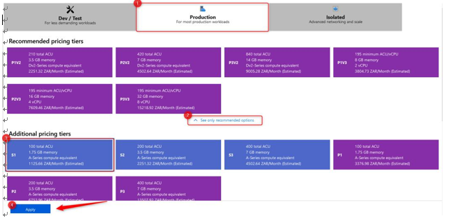
Here, you scaled down your application from the S1 SKU to the B1 SKU, which shows how easy it is to change its size. Note that the application will restart upon being resized. You will need to resize the application so that it’s a production SKU for the next exercise. When changing its size, select Production and click See additional options. Click S1 and then Apply:

Figure 12.13 – Scaling up to S1

Now, let’s learn how to scale out horizontally:

  1. Navigate to the App Service plan you worked on in the previous exercise.
  2. From the left menu blade, under theSettings context, click Scale out (App Service plan).
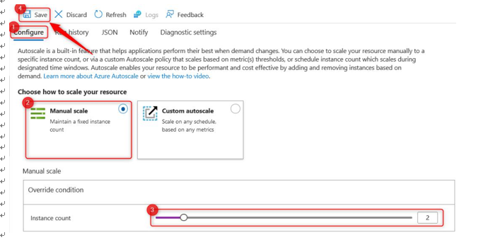
  3. Note that you can choose either Manual scale or Custom autoscale. Here, it would be best to manually scale since you are working on Dev / Test workloads, but for production workloads, you should choose Custom autoscale. Change Instance count to 2 and click Save:

Figure 12.14 – Manual scale

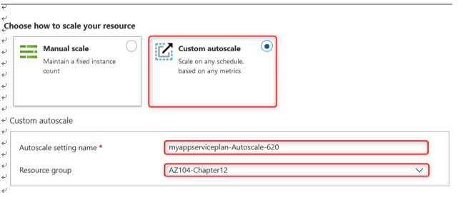
  1. Now, change the setting to Custom autoscale. Enter a name for your Autoscale setting name and select your Resource group:

Figure 12.15 – Custom autoscale

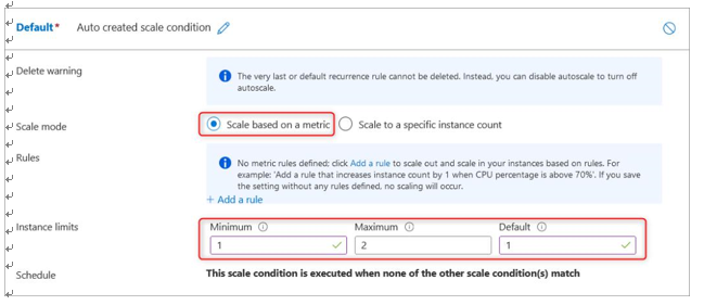
For our Default scale condition, we will create the first one using Scale based on a metric for Scale mode, and we will set Instance limits to 1 for Minimum, 2 for Maximum, and 1 for Default. Then, click Add a rule:

Figure 12.16 – Scale condition setup

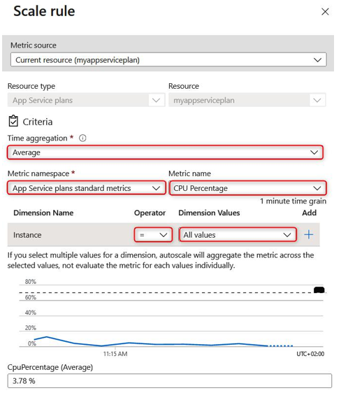
  1. For the Criteria section, set Time aggregation to Average, Metric namespace to App Service plans standard metrics, and Metric name to CPU Percentage. Set Operator to = and Dimension Values to All values (this means any web app).

Note the timeline chart at the bottom of the screen, which indicates the average CPU percentage that you have experienced over time, with the average also written below it. In this case, it is 3.78 %:

Figure 12.17 – Scale rule

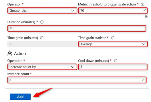
  1. Below the CPUPercentage (Average) section, you will notice some other configuration options. Set Operator to Greater than and Metric threshold to trigger scale action to 70. Then, set Duration (minutes) to 10 and Time grain statistic to Average. This will define a rule that states that when the CPU average percentage reaches greater than 70% usage over 10 minutes, it will trigger an Action.
  2. For the Action section, set Operation to Increase count by, Cool down (minutes) to 5, and Instance count to 1. This will increase the instance count of the running web applications by 1 when the criteria that we configured in step 7 have been identified. Once triggered, a cooldown period will occur, where no further actions can be performed until the cooldown window has elapsed. In this case, it is 5 minutes. If the criteria for scaling are observed again after this cooldown period, then the action will be triggered again. Click Add:

Figure 12.18 – Configuring a scale rule – Thresholds

  1. You have just configured a rule for scaling your application up in terms of its instance count, but what if you would like the application to scale back down when you don’t need as many instances anymore? You would need to configure a new scale condition to trigger a scale-down action you would like to perform. Click + Add a rule below the Scale out rule you just created:

Figure 12.19 – Add a rule

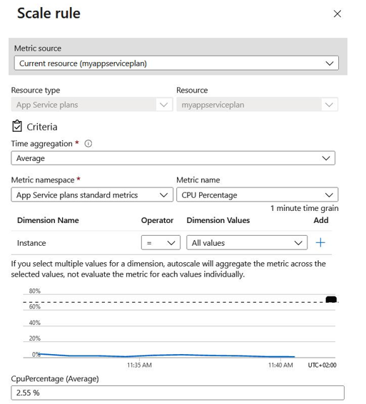
  1. For the Criteria section, set Time aggregation to Average, Metric namespace to App Service plans standard metrics, and Metric name to CPU Percentage. Set Operator to = and Dimension Values to All values (this means any web app).

Note that the timeline chart at the bottom of the screen indicates the CPU percentage average that you have experienced over time, with the average also written below it. In this case, it is 2.55 %:

Figure 12.20 – Scale rule

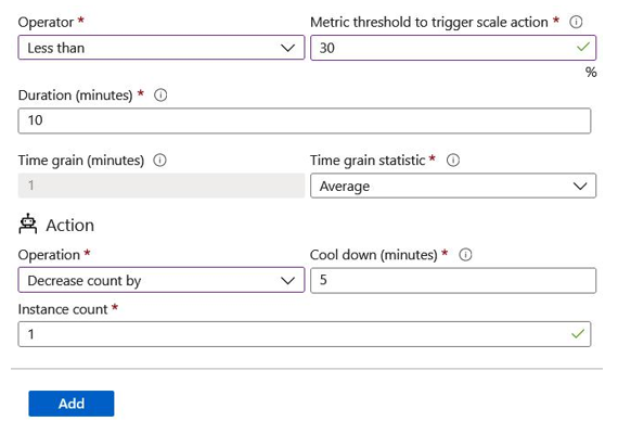
  1. Below the CPUPercentage (Average) section, you will notice some other configuration options. Set Operator to Less than and Metric threshold to trigger scale action to 30. Then, set Duration (minutes) to 10 and Time grain statistic to Average. This will define a rule that states that when the CPU average percentage reaches less than 30% usage over 10 minutes, it will trigger an Action.
  2. For the Action section, set Operation to Decrease count by, Cool down (minutes) to 5, and Instance count to 1. This will decrease the instance count of the running web applications by 1 when the criteria that we configured in Step 11 have been identified. Once triggered, there will be a cooldown period where no further actions can be performed until the cooldown window has elapsed. In this case, it is 5 minutes. If the criteria for scaling are observed again after this cooldown period, then the action will be triggered again. Click Add:

Figure 12.21 – Scale rule – Threshold and Action sections

  1. Click Save.

Now that you have configured your autoscale rules using the Azure portal, let’s learn how to use PowerShell to do the same.

More Details
Jan 12, 2023
Securing an app service 3 – Creating and Configuring App Services
  1. You can also consider using backups and disaster recovery (DR) for your applications. But why? If your application becomes compromised and you need to perform restoration tasks, without backups, you would potentially lose all your critical data. Therefore, anything that could cause the application to go offline or become inaccessible would compromise the security of the application. The same is true for DR; if you can’t restore an active instance of the application, its security is compromised as potential usage of the application will be restricted, which could lead to several other issues for an organization and a loss of revenue.
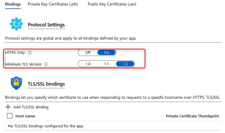
  2. The next menu you should click through is TLS/SSL settings. On this blade, select the Bindings tab and ensure that HTTPS Only is set to On. This ensures that all your traffic is encrypted and secured to the application, where HTTP traffic allows compromises to occur and should always be configured to forward all HTTP requests to HTTPS. HTTP communicates in clear text, so any credentials or sensitive information that’s sent would be visible to anyone that could intercept the traffic, which is highly insecure. HTTPS requires a certificate, which can be configured within the same blade. Azure offers one free certificate per web application for a single domain:

Figure 12.31 – Protocol Settings – TLS/SSL bindings

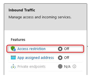
  1. Next, click on the Networking option from the left menu of the application. Networking is an interesting topic for your applications and can result in many sleepless nights if it’s not planned and managed correctly. The rule of thumb for hardening your network is to secure your perimeters and isolate traffic via perimeters, as well as by adopting the Zero Trust model (where you don’t trust any application or service that doesn’t intend to communicate with the application). It should only be public-facing if your application requires public access. You will also want to consider a Web Application Firewall (WAF) and firewall service for public traffic, as well as something internal. Azure provides several options for privatizing traffic for your application and it’s important to understand your traffic flow when you’re considering your implementation. The first item you must configure here is Access restriction, which applies to inbound traffic. This will act as a whitelist or blacklist for your traffic, depending on how you configure your rules. To configure this, click Access restriction:

Figure 12.32 – Network settings – Inbound Traffic 1

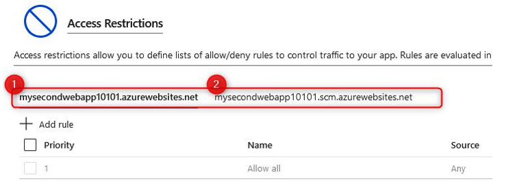
  1. As the most secure option, you should restrict all traffic except for your allowed rules. You will notice that you can configure your restriction rules for two different endpoints. The first is the public endpoint for your application, while the second has a suffix starting withscm, which is used for the Kudu console and web deployments. To see the available configuration options, click + Add rule:

Figure 12.33 – Network settings – Access Restrictions

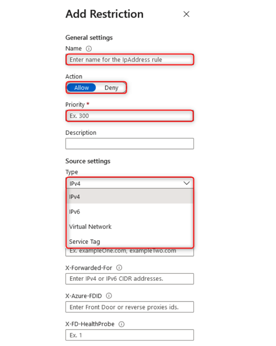
  1. On the Add Restriction pane that appears, you can set a Name; enter something meaningful. Next, you must decide on an Action, which can be either Allow
    or Deny; click Allow. You can also enter a Priority and, optionally, a Description. The next option, Type, is very important as it is used to determine the type of restriction that’s being implemented and how the rule is invoked. The default configuration is IPv4, which is limited to a known IPv4 address or range (usually a public address or range) and is added to the IP Address Block text box. When entering a range, you can enter it in CIDR notation, with a single IP being /32 for the CIDR. Enter an IP address. IPv6 works in the same fashion except for IPv6 addresses or ranges. The Virtual Network source option allows you to select a network that you have configured previously to allow traffic through. The final option is Service Tag. Click Add rule:

Figure 12.34 – Add Restriction

More Details
Jan 10, 2023
Securing an app service – Creating and Configuring App Services

Securing an app service

There are several mechanisms you can use to enhance the security of your application on Azure. As part of the AZ-104 exam, we will explore the configuration options that are native to the web application directly. However, note that for real-world implementations, you should investigate additional measures for enhancing the security of your applications, such as employing a firewall – especially a web application firewall – for your web-based applications. These services provide traffic that’s in line with your application and scan for disallowed or heuristic behavior.

In this exercise, we will look at various native application configurations that can be used to increase the security level of your app services:

  1. Navigate to the App Service plan you worked on in the previous exercise.
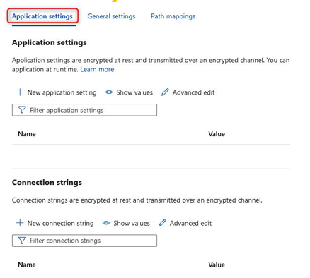
  2. From the left menu blade, under theSettings context, click Configuration. The first tab you will be greeted with is called Application settings. Application settings are variables that are presented securely to your application, but they can be configured externally from the application code. This enhances security by obfuscating the password from code and prevents developers that don’t have RBAC permissions on the Azure portal for the App Service resource from seeing sensitive data, such as secrets that may be stored under Application settings. The other item that can be configured is Connection strings:

Figure 12.22 – Application settings

  1. The next tab is General settings. Here, you will want to ensure File Transfer Protocol (FTP) traffic is conducted securely if it’s allowed by your organizational policies. FTP is a technology that enables file transfer operations for your systems. It is commonly used by developers to upload code to the system; an alternative, as we explored in the previous chapter, is to use a source code repository such as Git. The most secure option is to disallow all FTP-based traffic as prevention is better than a cure. However, since many applications require developers to be able to upload their code, changing the FTP transfer protocol that’s being used is the next best option. Setting traffic to FTPS only ensures that the FTP traffic is conducted over an HTTPS tunnel, meaning that all the data is encrypted. So, even if it is intercepted, it is less likely to be compromised. Set this to FTPS only for
    this exercise:

Figure 12.23 – FTP state

  1. Click Save at the top of the screen:

Figure 12.24 – Options menu

Note that after clicking Save, you will be warned that the application needs to be restarted.

  1. The last tab that can be configured in the General settings menu is Path mappings. We won’t explore this here.
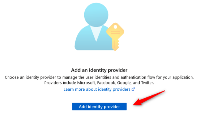
  2. From the left menu pane, clickAuthentication. This blade contains the configuration settings related to authentication, the type of identity provider service that’s being used, and the authentication flow. To explore the available configurations, click Add identity provider:

Figure 12.25 – Add identity provider

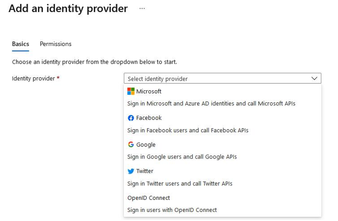
  1. At the time of writing, you can choose from several identity providers – that is, Microsoft, Facebook, Google, Twitter, and OpenID Connect. ClickMicrosoft:

Figure 12.26 – Add an identity provider

More Details
Nov 4, 2022
Configuring custom domain names – Creating and Configuring App Services

Configuring custom domain names

Custom domains allow you to connect to your web application using the public DNS name that you have chosen for your application. To do this, you need to own the respective domain and prove that you have authority over it. Your custom domain could be, for example, www.yourapp.com. There are several providers for purchasing a domain, though this is outside the scope of this book. For suggestions on getting started, you could buy directly from Microsoft, which also leverages GoDaddy. To configure a custom domain, follow these steps:

  1. Navigate to the App Service plan you worked on in the previous exercises.
  2. From the left menu blade, theSettings, click Custom domains. From the blade that appears, click + Add custom domain.
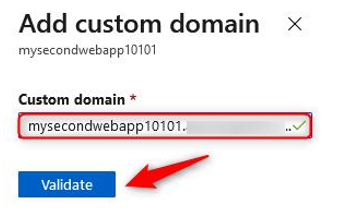
  3. Enter a Custom domain name of your choice, such as www.yourapp.com (this must be for a domain that you own). Click Validate:

Figure 12.42 – Add custom domain

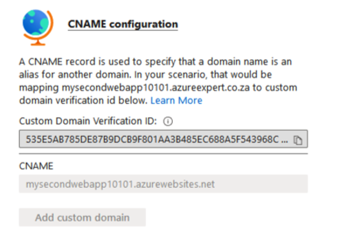
  1. You will be presented with a screen that gives you a Custom Domain Verification ID:

Figure 12.43 – CName configuration

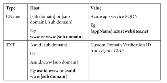
Copy this ID and create a new CName and TXT record for your domain, as follows. These values will be used to determine that you have authority over the domain you have specified:

Top Tip

You can also map custom domains using A records or a wildcard (*) CNAME record. Go to https://docs.microsoft.com/en-us/azure/ app-service/app-service-web-tutorial-custom-domain?tabs=a%2Cazurecli#dns-record-types for more details.

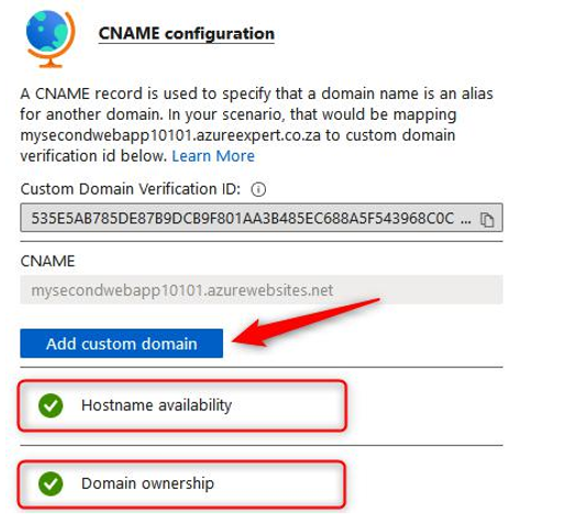
  1. Once completed, click the Validate button again.
  2. The following screenshot shows an example of the TXT and CName records that you may have created with your domain host (all the providers have slightly different configurations):

Figure 12.44 – TXT and CName records

  1. You will get two successful messages after clicking the Validate button. Now, click Add custom domain:

Figure 12.45 – Add custom domain

  1. With that, your custom domain has been added. However, you now have an entry on your screen that shows that this endpoint is not secure. You will need to add a certificate to make it secure. Click TLS/SSL settings from the left menu:

Figure 12.46 – Insecure custom domain

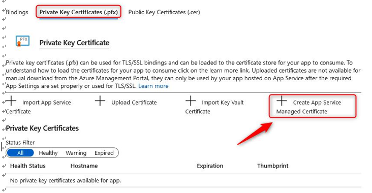
  1. Click the Private Key Certificates (.pfx) tab. Then, click + Create App Service Managed Certificate:

Figure 12.47 – Private Key Certificate

  1. Once Azure has analyzed the eligibility of the hostname, click Create. Azure allows one certificate per web app to be generated by the platform for your custom domain. This can save you a lot of money as, typically, you will need to procure a certificate from a third-party vendor. Your certificate will be valid for 6 months once it’s been created.
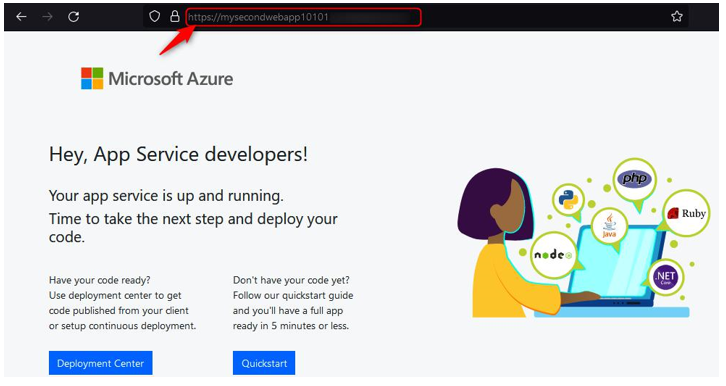
  2. DNS propagation can take up to 48 hours to occur, though sometimes, this can happen within minutes, depending on whether your DNS was used and the Time to Live (TTL) setting has been configured. You should now be able to browse your web app using the custom domain you configured. Note that you can connect using HTTPS and get a valid certificate check:

Figure 12.48 – Browsing to your custom domain

You now know how to configure a custom domain for your web app within Azure, as well as how to generate a valid certificate using the platform for a certified secure HTTPS connection. Typically, this can be done for production-based applications that are exposed to the internet and it is a common administrative duty for those that work in organizations that utilize many web applications. In the next section, you will learn how to configure backups for your applications.

More Details
May 4, 2022
Configuring deployment settings – Creating and Configuring App Services

Configuring deployment settings

There are several deployment settings related to your app service that you should be aware of. These allow you to upload your code or manage source control and deployment slots.

Deployment slots are logical segmentations of your application that can pertain to different environments and versions. Let’s say you have an application that is running in production mode (meaning it’s live and operational), and you want to work on some new code updates to introduce new features to the next version of your application. Typically, you would work on this in a test environment and deploy it accordingly to the production environment, once you felt that adequate testing had been performed before deploying anything to production.

Well, deployment slots provide a solution that allows you to deploy code to these slots to test the different functions and features of your applications, as well as code updates. You can run your primary deployment slot as the native application and deploy additional slots, such as TEST, that can be used for your new code. You have the option to swap deployment slots and revert at any time. The transition period is quick and enables a different paradigm in app management. You can, for instance, switch to the TEST slot and find that your application is not connecting to the required services and is slow. In this case, you can quickly flip back to the original code you had before any changes were made.

Let’s look at a brief configuration of a deployment slot before proceeding to the next part of this section:

  1. Navigate to the App Service plan you worked on in the previous exercises.
  2. From the left menu blade, underDeployment, click Deployment slots.
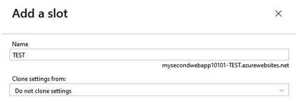
  3. From the top of the blade, click + Add Slot. Enter a Name – in this case, TEST – and leave Clone settings from set to Do no clone settings. Click Add, then Close:

Figure 12.60 – Add a slot

  1. The name you chose previously will form part of the FQDN for the deployment slot so that it can be accessed as a normal application, as shown in the preceding screenshot.
  2. Click Swap and set your Source as the new deployment slot you just created, and Target as the current slot. Click Swap, then Close:

Figure 12.61 – Swap

Now that you know about deployment slots, let’s explore the Deployment Center:

  1. Navigate to the App Service plan you worked on in the previous exercises.
  2. From the left menu blade, underDeployment, click Deployment Center. Click the Settings tab.
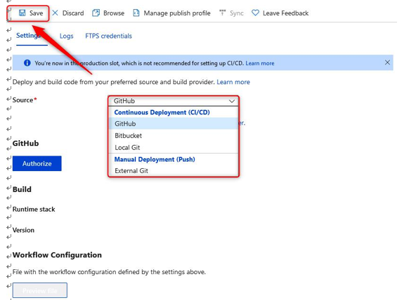
  3. Here, you have the option to deploy code from a Continuous Integration/ Continuous Deployment (CI/CD) tool. At the time of writing, the available options are GitHub, Bitbucket, and Local Git. Once you have chosen your Source CI/CD tool, you must Authorize your account and click Save:

Figure 12.62 – Deployment Center – Settings

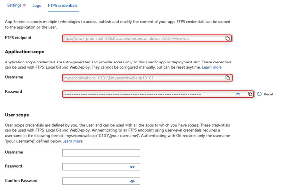
  1. Click the FTPS credentials tab and note FTPS endpoint. Application scope is an automatically generated Username and Password that’s limited to your application and deployment slot. You can use this to connect to your FTPS endpoint. You can also define a User scope and create a username and password:

Figure 12.63 – Deployment Center – FTPS credentials

With that, you have learned about the deployment settings that are available to you for your app services. You should now feel comfortable navigating this component of Azure App Service as you know where to integrate CI/CD and where to find your FTPS credentials so that you can modify your application code. Next, we will summarize what we covered in this chapter.

Summary

In this chapter, we covered what an App Service is within Azure, the role of App Service plans and why they are essential to your App Service, and how to deploy an application, including how to manage its settings and configurations and how to secure it. Then, we explored and discussed various networking configurations for your application and the considerations you need to have when configuring these settings. You should now feel confident working with applications on Azure using App Service.

In the next chapter, we will cover some examples of deploying and managing compute services within Azure. There will be a VM lab, a container lab, and an App Service lab. After following these examples, you will feel more comfortable working with Azure compute services.

More Details
Jan 11, 2022
Deploying an Azure Container Instances lab – Practice Labs – Deploying and Managing Azure Compute Resources

Deploying an Azure Container Instances lab

This lab willguide you through creating a container group using Azure Container Instances using a Docker image and testing connectivity to your deployed containers.

Estimated time: 20 minutes.

Lab method: PowerShell and the Azure portal.

Lab scenario: In this lab, you play the role of an administrator who is looking to reduce their container management activities. Your organization, Contoso, has several virtualized workloads, and you want to explore whether these can be run from Azure Container Instances using Docker images.

Visit the following URL to the official Microsoft Learning GitHub labs, where you will be guided through each task step by step to achieve the following objectives.

Lab objectives:

I.  Task one: Use Azure Container Instances to host your container.

II. Task two: Confirm connectivity to your container and functionality.

Lab URL: https://microsoftlearning.github.io/AZ-104-MicrosoftAzureAdministrator/Instructions/Labs/LAB_09b-Implement_Azure_Container_Instances.html.

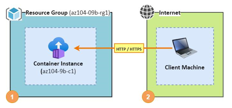
Lab architecture diagram:

The following diagram illustrates the different steps involved in the exercise:

Figure 13.4 – Deploying an Azure container instance – architecture diagram

After running through this lab, you should now feel confident to deploy container instances to Azure. The next lab will take you through using Azure Kubernetes Service for the orchestration of your container instance deployments.

Deploying an Azure Kubernetes Service lab

This labwill guide you through setting up an Azure Kubernetes Service instance and deploying an NGINX pod for your multi-tier applications. You will implement node scaling as part of the exercise and learn to leverage Kubernetes as an orchestration service in Azure.

Estimated time: 40 minutes.

Lab method: PowerShell and the Azure portal.

Lab scenario: In this lab, you play the role of an administrator who is looking to reduce container management activities and implement container orchestration services. Your organization, Contoso, has several multi-tier applications that are not suitable for Azure Container Instances. You want to explore running these through Kubernetes, and since Azure has Azure Kubernetes Service (AKS), you want to leverage this to minimize administrative effort and complexity in deploying your solution.

Visit the following URL to the official Microsoft Learning GitHub labs, where you will be guided through each task step by step to achieve the following objectives.

Lab objectives:

  1. Task one: Register the required resource providers for your subscription.

II. Task two: Deploy AKS.

III. Task three: Deploy your AKS pods.

IV. Task four: Configure scaling for your AKS cluster.

Lab URL: https://microsoftlearning.github.io/AZ-104-MicrosoftAzureAdministrator/Instructions/Labs/LAB_09c-Implement_Azure_Kubernetes_Service.html.

Lab architecture diagram:

The following diagram illustrates the different steps involved in the exercise:

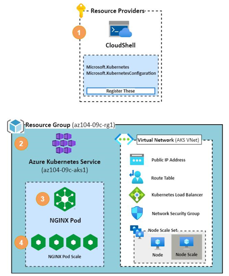
Figure 13.5 – Deploying an Azure container instance – architecture diagram

After working through these previous labs, you should feel confident working with containers on Azure. You are also familiar with some aspects of the Kubernetes service, which can be used for the orchestration of your container instances. You’ve also experienced managing scale using these tools and will be prepared for performing this aspect of your role going forward. The next lab will explore working with Web App service on Azure.

More Details
Aug 8, 2021
Creating and configuring virtual networks, including peering 2 – Implementing and Managing Virtual Networking

One of the exam objectives for this chapter is to gain the ability to configure VNet peering. VNet peering is when two or more VNets are linked with each other so that traffic can be sent from one network to another. There are two types of VNet peering:

• VNet peering: Connects VNets with the same region. There is also a cost associated with inbound and outbound data transfers for VNet peering.

• Global VNet peering: Connects VNets across different regions. This is more costly than VNet peering within the same region.

When using the Azure portal to configure VNet peering, there are a few settings that you should be aware of:

• Traffic to a remote VNet: Allows communication between two VNets, as this allows the remote VNet address space to be included as a part of the virtual-network tags.

• Traffic forwarded from a remote VNet: Allows traffic forwarded by a VNet appliance in a VNet that did not originate from the original VNet to flow via VNet peering to the other VNet.

• Virtual network gateway or Route Server: This is relevant when a VNet gateway is deployed to the VNet and needs traffic from the peered VNet to flow through the gateway.

• Virtual network deployment model: Select which deployment model you want with the peered VNet. This will either be classic or the standard resource manager method.

Let’s go ahead and configure VNet peering. To do this, we need to create another VNet first using these steps:

  1. In PowerShell, use the following command:

Connect-AzAccount

  1. Next, the following command will create another VNet, which will include a subnet that links to the VNet in the same RG that we created earlier in this chapter:

$vnet = @{

Name = ‘DemoVNet_2’

ResourceGroupName = ‘VNet_Demo_ResourceGroup’ Location = ‘WestEurope’ AddressPrefix = ‘192.168.0.0/24’
}

$virtualNetwork = New-AzVirtualNetwork @vnet $subnet = @{

Name = ‘Main_Subnet’

VirtualNetwork = $virtualNetwork

AddressPrefix = ‘192.168.0.0/24’

}

$subnetConfig = Add-AzVirtualNetworkSubnetConfig @subnet $virtualNetwork | Set-AzVirtualNetwork

  1. Sign in to the Azure portal by visiting https://portal.azure.com and navigating to the RG:

Figure 14.5 – Both VNets showing in the Azure portal

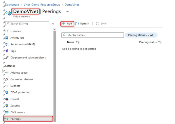
  1. Next, select DemoVNet, and under Peerings, select Add:

Figure 14.6 – Configuring VNet peering

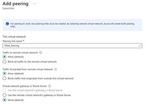
  1. Next, configure the peering link name, as shown in Figure 14.7, and set the following fields as Allow (default):

I. Traffic to remove virtual network

II. Traffic forwarded from remote virtual network

III. Virtual network gateway or Route Server:

Figure 14.7 – Configuring VNet peering for DemoVNet

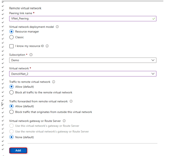
  1. Next, give the remote peering link a name of VNet_Peering, select the VNet, and configure the following fields as Allow (default):

I. Traffic to remove virtual network

II. Traffic forwarded from remote virtual network III. Virtual network gateway or Route Server Next, click on Add:

Figure 14.8 – Configuring VNet peering for DemoVNet_2

  1. Give the peering status a few minutes to enforce the peering. The final peering status will be Connected:

Figure 14.9 – Successfully configured peering between VNets

In this section, we had a look at how virtual networking works in Azure as well as how to create a VNet and subnet via PowerShell. We also had a look at how to configure VNet peering between two VNets.

We encourage you to read up on Azure virtual networking and VNet peering further by using the following links:

• https://docs.microsoft.com/en-us/azure/virtual-network/ quick-create-powershell

• https://docs.microsoft.com/en-us/azure/virtual-network/ manage-virtual-network

• https://docs.microsoft.com/en-us/azure/virtual-network/ virtual-network-peering-overview

More Details
Aug 7, 2021
Creating and configuring virtual networks, including peering – Implementing and Managing Virtual Networking

Creating and configuring virtual networks, including peering
In this section, we are going to look at how to create and configure Virtual Networks (VNets) and peering. Let’s start with an overview of VNets and IP addressing and how it works within Azure.

A VNet overview

Before we dive into how to configure VNets, let’s take a moment to understand what VNets are and what their purpose is. A VNet in Azure is a representation of your network in the cloud that is used to connect resources such as virtual machines and other services to each other.

Unlike traditional networks, which make use of physical cables, switches, and routers to connect resources, VNets are completely software-based. VNets have isolated IP ranges, and resources placed inside a VNet do not talk to the resources in other VNets by default. To allow resources in two different VNets to talk to each other, you would need to connect the VNets using VNet peering.

Important Note

All resources deployed to a VNet must reside in the same region.

An IP addressing overview

Azure supports both private and public IP addresses. Private IP addresses are assigned within the VNet in order to communicate with other resources within it and cannot be accessed via the internet by design. Public IP addresses are internet-facing by design and can be assigned to a virtual machine (VM) or other resources, such as VPN gateways.

Both private and public IP addresses can be configured to be dynamic or static. Dynamic IP addresses change when the host or resource is restarted, whereas static IP addresses do not change even if the resources are restarted.

Dynamic IP addresses are automatically assigned by Azure based on the subnet range. When a VM is deallocated (stopped), the dynamic IP address goes back into the pool of IP addresses that can be assigned to other resources again. By default, private IP addresses are dynamic but can be changed to static via the Azure portal when needed.

Static public IP addresses are random public IP addresses that do not change after being assigned to a resource. Unlike a dynamic IP address that changes when a resource is restarted, the static IP address is persisted. Public IPs are usually assigned to internet-facing resources such as VPN gateways and, in some instances, VMs.

Now that we have covered the basic networking components, let’s go ahead and configure a VNet via PowerShell:

  1. First, we need to connect to our Azure tenant by using the following PowerShell command:

Connect-AzAccount

The output appears as shown in the following screenshot:

Figure 14.1 – Connecting to the Azure tenant via PowerShell

  1. If you have multiple Azure subscriptions, you can use the following PowerShell command to select a specific subscription:

Select-AzSubscription -SubscriptionId “your-subscription-id”

  1. Now that we have selected our Azure tenant and subscription, let’s go ahead and create a new Resource Group (RG):

New-AzResourceGroup -Name VNet_Demo_ResourceGroup -Location WestEurope

The following screenshot shows the output of the command:

Figure 14.2 – A new RG is created

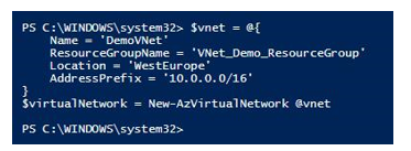
  1. Next, let’s create the VNet:

$vnet = @{

Name = ‘DemoVNet’

ResourceGroupName = ‘VNet_Demo_ResourceGroup’ Location = ‘WestEurope’ AddressPrefix = ‘10.0.0.0/16’

}

$virtualNetwork = New-AzVirtualNetwork @vnet

The following screenshot shows the output of the command:

Figure 14.3 – A new VNet is created

  1. Next, we need to configure a subnet range within the VNet:

$subnet = @{

Name = ‘Demo_Subnet’

VirtualNetwork = $virtualNetwork

AddressPrefix = ‘10.0.0.0/24’

Creating and configuring virtual networks, including peering 455

}

$subnetConfig = Add-AzVirtualNetworkSubnetConfig @subnet

  1. Lastly, we need to associate the newly created subnet to the VNet with the help of the following command:

$virtualNetwork | Set-AzVirtualNetwork

  1. Verify in the Azure portal that the new VNet and subnet have been created:

Figure 14.4 – The VNet and subnet showing in the Azure portal

Hint

If you are getting an error stating that scripts are disabled on your system, you can use the following PowerShell command to resolve it: set-executionpolicy unrestricted –Scope CurrentUser.

More Details